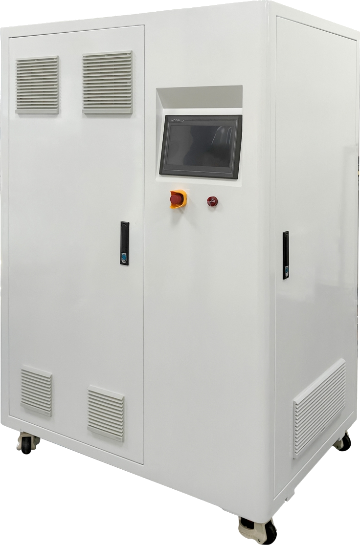
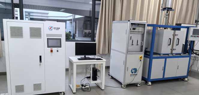
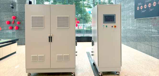
Integrated PEM hydrogen generators for laboratories, clean-energy teaching and renewable microgrids. Water treatment, power conversion, system control and protective logic are engineered into one deployment-ready platform.
01Integrated ArchitectureCore subsystems engineered as one platform
02On-Demand ProductionGenerate hydrogen near the point of use
03Application ReviewConfiguration checked before quotation
SYSTEM WORKFLOW
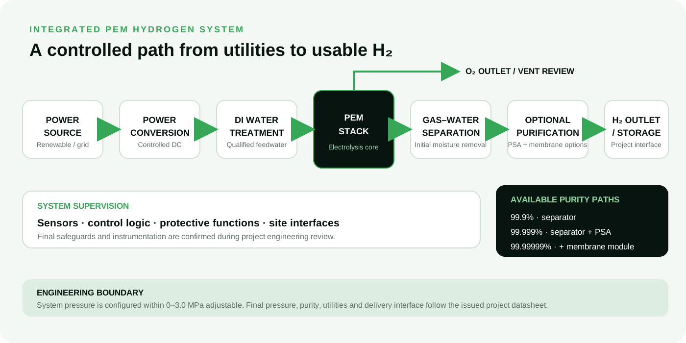
How an integrated PEM hydrogen system works.
Power, deionized water, gas handling, purification and controls operate as one engineered path. The diagram clarifies the functional boundary before model selection and site review.
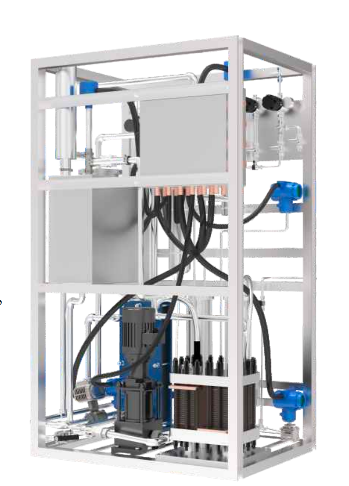
Functional workflow for project discussion. Final equipment scope and safeguards follow the issued project datasheet.REAL SYSTEM REFERENCE · COMPONENT ARRANGEMENT VARIES BY PROJECT
30-SECOND APPLICATION ROUTER
Start with the job. Then size the system.
Choose your use case for a recommended starting point. Final model, utilities and compliance scope are confirmed during engineering review.
RECOMMENDED STARTING POINT
ST-0.6
A compact starting point for on-demand hydrogen in analytical and research workflows.
Water content derived from dew-point measurement; oxygen measured with an oxygen-in-hydrogen analyzer; hydrogen purity calculated by difference after deducting water and oxygen.
Feed Water
ASTM D1193 Type I DI >10 MΩ·cm
ASTM D1193 Type I DI >10 MΩ·cm
1–4 barg feed pressure*
Power Supply
220 V AC
380 V AC
220 V AC
DC Energy Consumption
4.4 kWh/Nm³ H₂
4.4 kWh/Nm³ H₂
>77.7% HHV efficiency
Dimensions (W × D × H)
1100 × 800 × 1600 mm
1100 × 800 × 1600 mm
500 × 400 × 505 mm with wheels
Net Weight
270 kg
400 kg
Confirm on issued datasheet
Operating Temperature
5–65°C
5–65°C
5–60°C
* Purity values are configured options tied to the stated treatment train. The system operating-pressure range is adjustable within 0–3.0 MPa; final outlet pressure and guaranteed purity are confirmed in the issued project documents.
ST-EDU · PV–H₂–FC TRAINERPhotovoltaic Hydrogen Production Demonstration Teaching UnitH₂ PRODUCTION & STORAGEPEM Water Electrolysis Hydrogen Production and Storage Demonstration SystemFUEL-CELL POWERHydrogen Fuel Cell Power Generation Demonstration System
DETAILED TECHNICAL SPECIFICATIONS
Category 2 · Visible Energy Conversion Training Systems
Three complementary teaching platforms for demonstrating renewable electricity, PEM electrolysis, hydrogen storage and fuel-cell power generation.
01 · SOLAR-TO-HYDROGEN-TO-POWER
ST-EDU · PV–H₂–FC Trainer
Photovoltaic Hydrogen Production Demonstration Teaching Unit
Subsystem
Engineering Parameter
Technical Specification
Photovoltaic Panel
Total Power
12 W
Rated Voltage
5 V
Rated Current
2.4 A
PEM Electrolyzer
Rated Hydrogen Production
40 mL/min
Power Supply Voltage
3 V
Rated Current
6 A
Fuel Cell
Rated Power
<1 W
Rated Voltage
0.9 V
Rated Current
1 A
Electrical Load
Power
0.019 W
Rated Voltage
1 V
Rated Current
18.9 mA
Teaching Unit
Dimensions (L × W × H)
750 × 420 × 330 mm
Weight
6.2 kg
02 · HYDROGEN PRODUCTION & STORAGE
PEM H₂ Production & Storage System
PEM Water Electrolysis Hydrogen Production and Storage Demonstration System
Subsystem
Engineering Parameter
Technical Specification
PEM Electrolyzer
Hydrogen Production Rate
500 mL/min
Oxygen Production Rate
250 mL/min
Power Supply Voltage
9 V
Power Supply Current
25 A
Dimensions without Lugs / Connections (L × W × H)
94 × 39 × 106 mm
Dimensions with Lugs / Connections (L × W × H)
109 × 58 × 106 mm
Solid-State Hydrogen Storage Tank
Cylinder Diameter
60 mm
Cylinder Height
258 mm
Weight
1.5 kg
Hydrogen Storage Capacity
>22 g
Hydrogen Filling Pressure
1.0 MPa
Continuous Hydrogen Discharge Pressure
0.6 MPa
Hydrogen Discharge Rate
>4 L/min
Demonstration System
Dimensions Excluding Stand (L × W × H)
1200 × 700 × 311 mm
Weight Excluding Stand
18 kg
Weight Including Stand
28 kg
03 · HYDROGEN-TO-POWER
Hydrogen Fuel Cell Power Generation System
Hydrogen Fuel Cell Power Generation Demonstration System
Subsystem
Engineering Parameter
Technical Specification
Solid-State Hydrogen Storage Tank
Cylinder Diameter
60 mm
Cylinder Height
258 mm
Weight
1.5 kg
Hydrogen Storage Capacity
>22 g
Hydrogen Filling Pressure
1.0 MPa
Continuous Hydrogen Discharge Pressure
0.6 MPa
Hydrogen Discharge Rate
>4 L/min
PEM Fuel Cell
Rated Voltage
19.8 V
Rated Current
10.2 A
Efficiency
≥45%
Hydrogen Supply Pressure
0.035–0.05 MPa
Required Hydrogen Purity
≥99.99% (CO ≤1 ppm)
Theoretical Hydrogen Consumption at Rated Power
2.89 L/min
Theoretical Air Consumption at Rated Power
114.6 L/min
Bare Stack Weight
1.43 kg
Demonstration System
Dimensions Excluding Stand (L × W × H)
1200 × 700 × 276 mm
Weight Excluding Stand
15 kg
Weight Including Stand
25 kg
Specifications are based on the current manufacturing-partner product document. Final configuration, interfaces and supplied modules are subject to the issued quotation and technical confirmation. Official ST model designations and downloadable datasheets will be added after document revision numbers are approved.
03
SCENARIO 3 · INTEGRATION-LED DEPLOYMENT
Off-Grid Renewable H₂ Storage
Convert surplus solar or wind power into hydrogen as part of a site-specific storage and power-balancing architecture.
2–5 Nm³/h standard cabinet starting range
Integration review for power, storage and controls
Documentation package aligned to system integrators
H₂ cabinet: 1300 × 950 × 1930 mm Power cabinet: 610 × 950 × 1930 mm
Net Weight
Confirm on issued datasheet
900 kg
* Purity values are configured options tied to the selected treatment train. The system operating-pressure range is adjustable within 0–3.0 MPa; final outlet pressure, guaranteed purity, interfaces and site operating envelope require project confirmation.
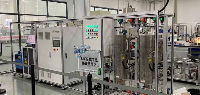
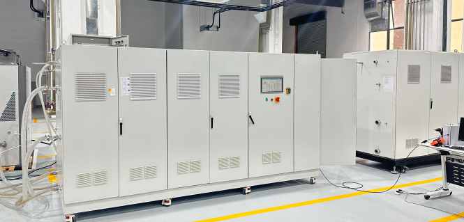
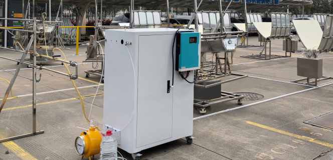
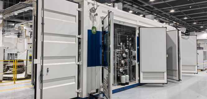
Selected manufacturing-partner equipment supplied for research, industrial-gas and renewable-energy applications. Project names are anonymized where required.
01 · RESEARCH PROCESS
SAF Synthesis Process Validation Hydrogen Supply Project
Hydrogen-production and process equipment supplied for sustainable aviation fuel synthesis validation.
Images show delivered or commissioned manufacturing-partner equipment. Final specifications, interfaces, documentation and supplied scope varied by application and contract.
SYSTEM PORTFOLIO
A clear starting point. A verified final specification.
Model values are aligned to the manufacturing partner's October 2025 English manual. The issued datasheet and quotation remain controlling.
* Lead time starts after technical configuration and order confirmation. One-year warranty applies to complete equipment; final commercial terms follow the signed quotation.
B2B DELIVERY LOGIC
What “plug-and-play” actually means.
01
Define
Application, hydrogen demand, operating profile and target market requirements.
02
Verify
Utility conditions, outlet interface, ventilation, controls and documentation scope.
03
Configure
Model selection, accessories and integration boundaries captured in the proposal.
04
Commission
Site-readiness checklist, remote guidance and acceptance criteria agreed before shipment.
STRUCTURED PROJECT BRIEF
Give our technical team the right starting data.
Complete the essentials for a model recommendation, utility review and quotation pathway.