Membrane Electrode Manufacturing
MEA preparation and repeatable process control for the agreed electrochemical design.
FACTORY-BACKED PEM STACK TECHNOLOGY
Our manufacturing partner develops the electrochemical core across MEA preparation, corrosion-resistant current collectors, bipolar plates, high-pressure sealing, stack design and testing. ST Hydrogen coordinates international specifications, documentation and commercial delivery.
PEM stack pressure boundary: model-specific maximum withstand ratings up to 3.5 MPa · Configured operating pressure and final outlet conditions require engineering review

Configurable ports, monitoring interfaces and compression architecture for the agreed operating envelope.
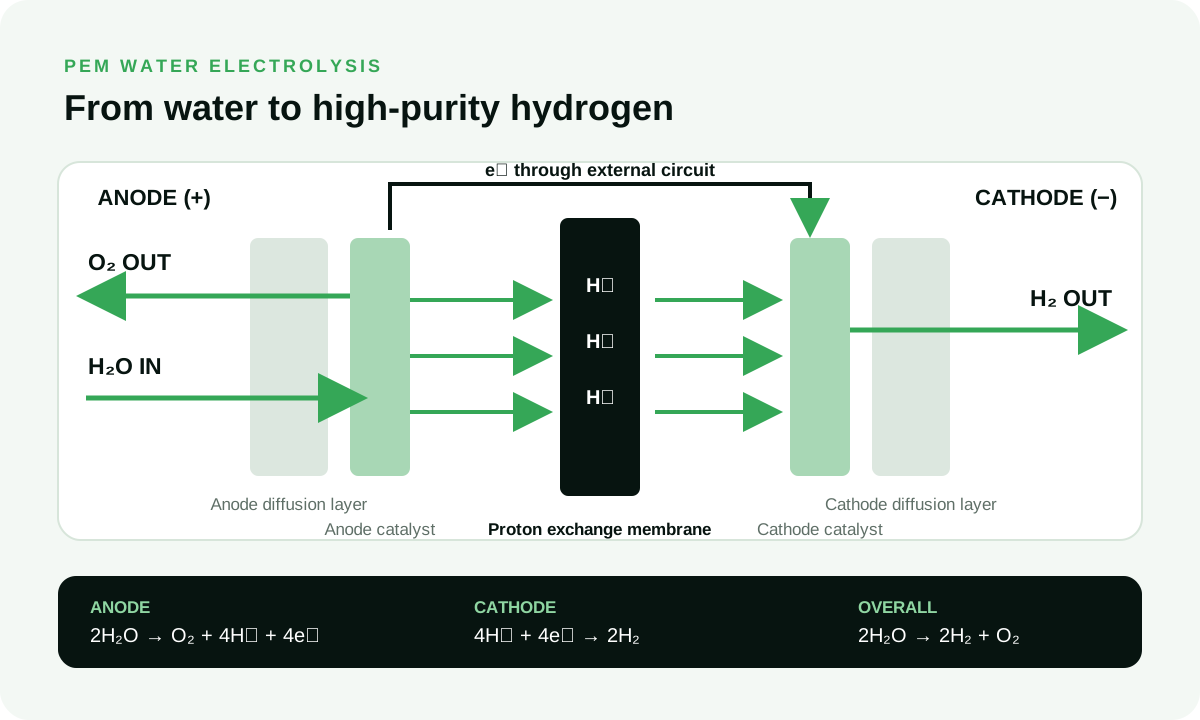
At the anode, deionized water is split into oxygen, protons and electrons. Protons cross the PEM while electrons travel through the external circuit; they recombine at the cathode to form hydrogen.
MEA preparation and repeatable process control for the agreed electrochemical design.
Collector material and surface-treatment choices reviewed against the operating environment.
Flow-field, manifold and manufacturability considerations developed around the target duty.
Seal geometry and compression strategy engineered for the specified pressure envelope.
Stack assembly, pressure checks and performance testing documented against agreed criteria.
Mechanical, electrical and control interfaces coordinated for OEM and cabinet integration.
Navigate by development stage: electrochemistry research, commercial system integration or controlled stack validation.
For university laboratories and MEA development teams that need repeatable test geometry, documented interfaces and clear I–V evidence.

Catalyst-loading sweeps, membrane degradation studies and early-stage electrochemistry evaluation.

Research-bench integration with pre-compressed architecture and configurable water-routing interfaces.

For advanced high-current research rigs requiring uniform flow distribution and cell-level performance evidence.
* Small-stack lead time is typically within 7 days after model, interfaces and order details are confirmed.
Core modules for integrators building power-to-gas pilots, hydrogen cabinets and renewable-energy systems.

Medium-scale stack platform for pilot cabinets and distributed hydrogen systems.
Higher-capacity commercial module with configurable sensor and mechanical interface options.
* Industrial-stack lead time is typically about one month after technical configuration and order confirmation.
Testing architectures for laboratory evaluation, factory acceptance testing and repeatable polarization characterization.

Automated I–V sweeping, data logging, water-temperature control and configurable pressure interlocks. LabVIEW interface support is reviewed per project.
Request bench specification
Compact initial-screening platform with visible flow path, basic electrical measurement and manual gas collection.
Request rig specificationRequest the engineering files your mechanical, electrical and controls teams need for an initial fit assessment.
Controlled files may require an NDA and an identified project before release.
Duty cycle, inlet conditions, output target and integration boundaries.
MEA, coating, flow field, compression, seals, ports and monitoring.
I–V curve, pressure test, leakage method and acceptance criteria.
Datasheet, ICD, STEP model and agreed quality documentation.
Give the electrochemistry and interface constraints required for a meaningful proposal.